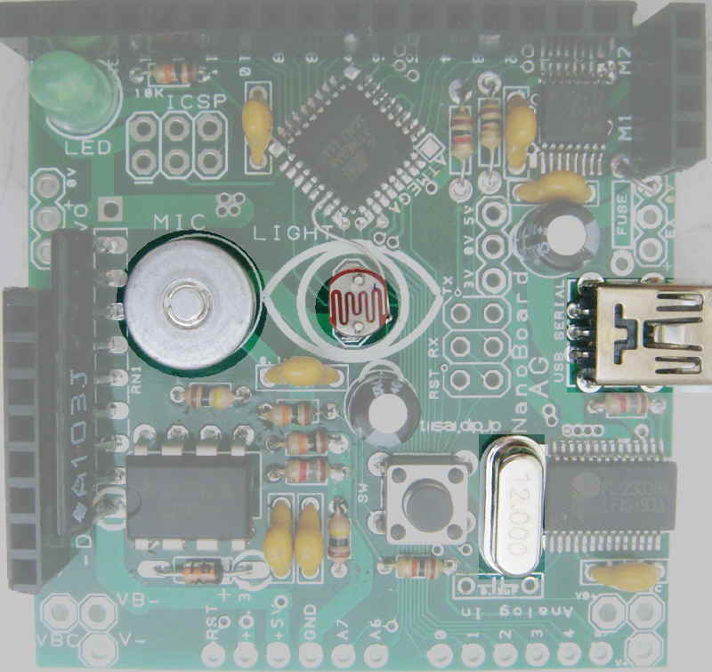
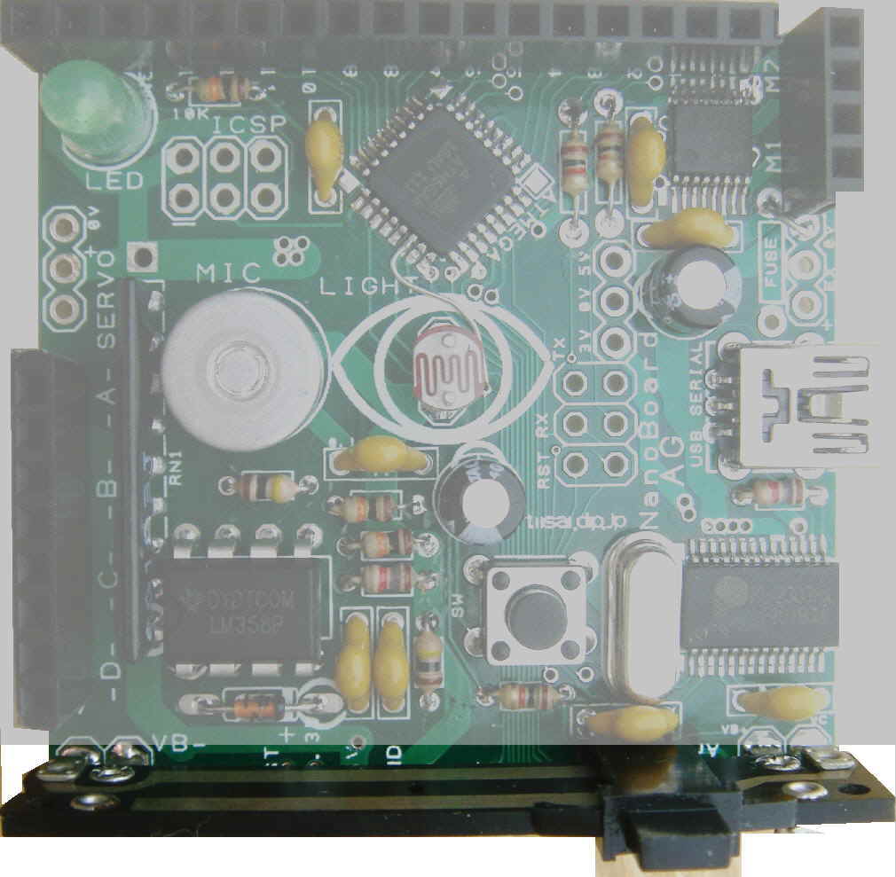
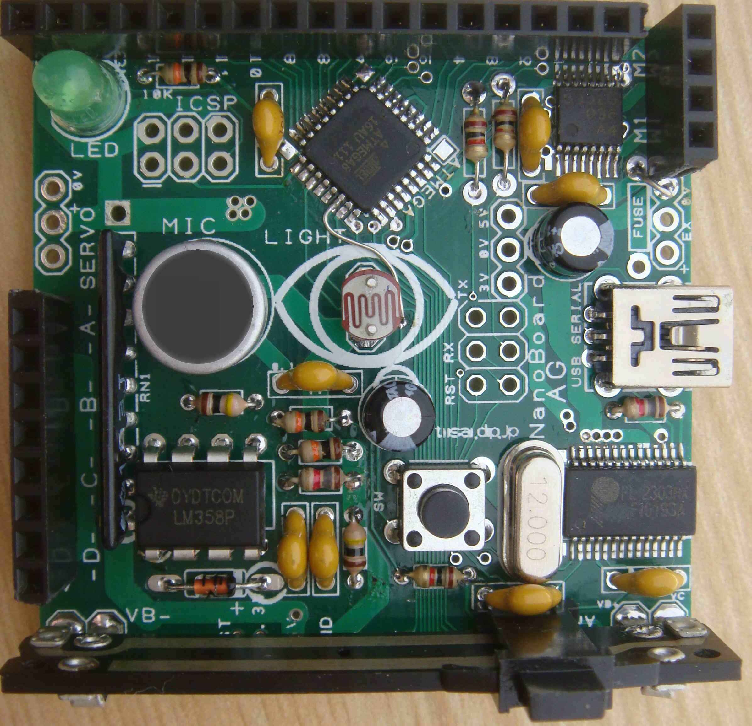
building NanoBoard AG1.1

NanoBoard AG 1.1 layout

–
Parts list ( assembly order )
order Qty value parts name
—————————————————–
1 3 330(1K) resistor 1/6W
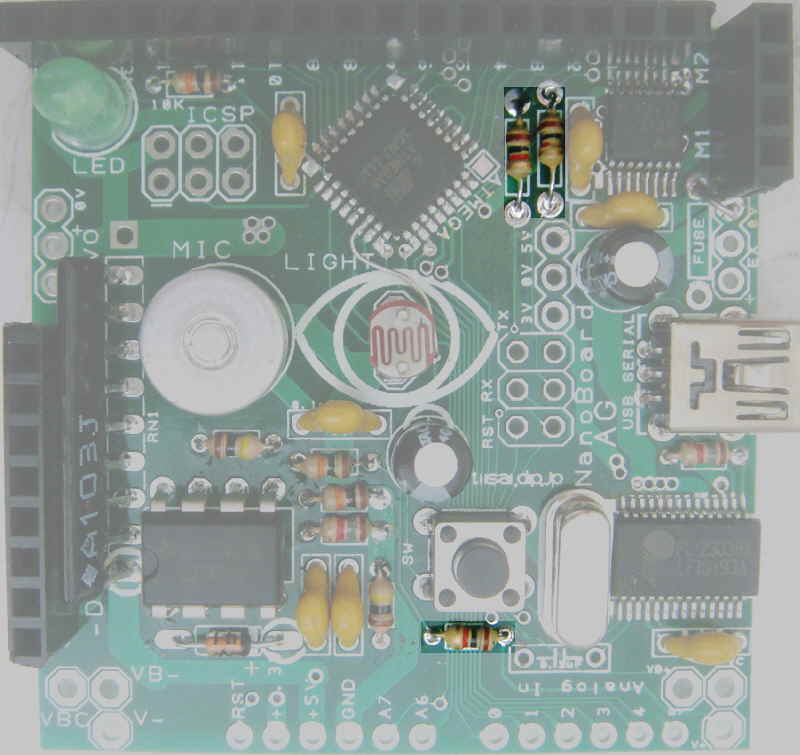
2 2 1.8K resistor 1/6W
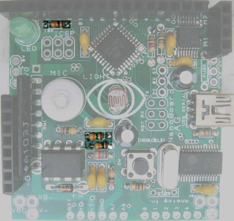
3 3 10K resistor 1/6W
4 2 100K resistor 1/6W
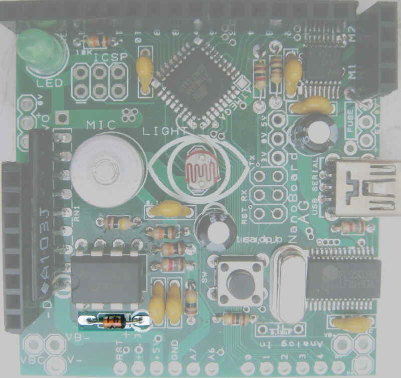
5 1 1N4148 diode
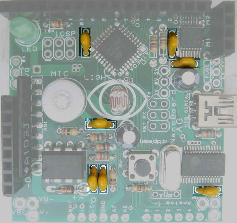
6 8 0.1uF ceramic capacitor (6 pcs for no-motor version)
7 1 12M Xtal
8 1 miniB USB connector
9 1 LED 3mm LED
–
10 1 CDS 5mm opto sensor
11 1 MIC 9.7mm MIC
12 1 47uF capacitor
13 1 LM358 opamp
14 1 10K x 8 resistor array
15 1 Pin socket
16 1 220uF capacitor (47uF for no-motor version)
17 1 PUSH SW tact switch
18 1 VR 50K-B slider
————————————————————
ATmega8 , PL-2302HX , TB6552 is assembled.
Assembling from low profile parts. Be careful with parts polarity .
PCB is delicate, re-work is difficult, Please make sure correct assembly, or you will damage PCB.
–
1) resistor 330 (orange-orange-brown) or 1K (brown-black-red) 3pcs.

–
2) resistor 1.8K (brown-gray-red) 2pcs. PCB silk is “1k8”.

–
3)resistor 10K (brown-black-orange) 3pcs.

–
4) resistor 100K (brown-black-yellow) 2pcs.

–
5) diode CHECK POLARITY!!


6) 0.1uF capacitor 8pcs.

–
7) cristal 12MHz
8 ) USB connector
9) 3mm LED. Check polarity, long lead(+) for white silk mark on PCB.

–
TESTING Board with PC .
– Download Scratch for NanoBoard.
– Install USB serial device driver,
Log-in PL2303 WEB site(User: GUEST, Password: GUEST)

- Click ”USB Serial/Paralell” on “USB Smart I/O controlers” menu at right side .

- Click ”Drivers & Software” under PL2303 menu.

- Download Windows/Mac/Linux driver middle of the web page
- install dowinloaded module.
–
– Install? Scratch, then make connection with Scratch on your PC.
– NanoBoardAG LED will blink when you start Scratch connection.
– Please check “ScratchBoard watcher” , all sensor value should be displayed randomly.
At this point, you can check MPU and USB chip works fine. You do not finish sensor soldering yet , random value will be displayed.
-Exit Scratch software, then plug off USB connector.
-If something wrong, Please check parts position and POLARITY, and heat each solder-pad again.
–
Continue soldering.
10) CDS float 5mm from PCB, solder one-pin , adjust assembly then solder another pin.
11) MIC
12) 47uF capacitor(small). Check polarity, long lead(+) for white silk mark on PCB.

–
13) LM358 OPAMP IC . Check polarity, pin1 for white silk mark on PCB.


14) 10K x 8 resistor array 9pin. Check polarity, pin1(white mark ) for white silk mark on PCB.

–
15) Pin socket connector. Cut to 4pin, 8pin, (17pin option) , then solder them.


–
16) 220uF capacitor(large). Check polarity, long lead(+) for white silk mark on PCB.
17) PUSH switch

–
18) slider 50K-B.


Slider pin does not fit with PCB hole.

bend slider pin to fit.
–
Finish solderling!! take some rest, then check assembly again before Power ON.

–
– Install? Scratch, USB serial device driver, Then make connection with Scratch on your PC.
–
DC motor generate big noise, it makes problem with MPU and PC.
You need to put? three 0.1uF capacitor(included in kit) between motor pins, and motor body.
Pin header connector is useful for easy connection with connector cabling. ( F.Y.I. )

–
The geared motor included in this kit is Low power type (5V 100mA). It works with USB power.
Please consider current restriction of moter driver (TB6552) spec , when you use other motor.
NanoBoardAG main page
V1.3